Symbols Of Electric Components
Key Notes :
1. What are Electrical Symbols?
- Electrical symbols are graphical representations of electrical components in circuits. These symbols are used in circuit diagrams to show how electrical components are connected.
2. Common Electrical Components and Their Symbols
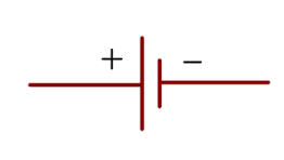
- Battery: Represented by a long line (positive) and a short line (negative).
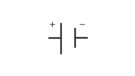
- Cell: A single battery, represented by one long and one short line.
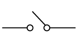
- Switch (Open): Two dots connected by a broken line, indicating an open switch.
- Switch (Closed): A solid line connecting two dots, indicating a closed switch.
- Light Bulb: A circle with a cross inside, representing the filament.
- Resistor: A zig-zag line, representing resistance in the circuit.
- Lamp: A circle with a cross inside and lines to represent the connections.
- Wire: A straight line, representing the conductor or wire.
- Power Source (AC): A circle with a sine wave inside, used for alternating current.
- Power Source (DC): A circle with a plus and minus sign, used for direct current.
- Fuse: A rectangle with a line through the center.
- Capacitor: Two parallel lines with a gap between them.
- Inductor: A series of loops or coils, representing an inductor.
3. Why Are Electrical Symbols Important?
- Clarity: They provide clear communication of circuit designs without confusion.
- Standardization: These symbols are universally recognized, making it easier for engineers and electricians around the world to work with circuits.
- Simplify Complex Circuits: Instead of drawing complex components, the symbols allow for easy representation of complex systems.
4. Basic Circuit Diagram Example
- A simple circuit might include:
- A battery supplying power,
- A switch to control the flow of current,
- A light bulb to show where the electrical energy is used.
5. Additional Components
- Diode: A triangle pointing to a line, representing the one-way flow of current.
- Transistor: A combination of lines with arrows, representing amplifying signals or acting as a switch.
- Ground: A series of horizontal lines stacked, representing the electrical ground.
Let’s practice!